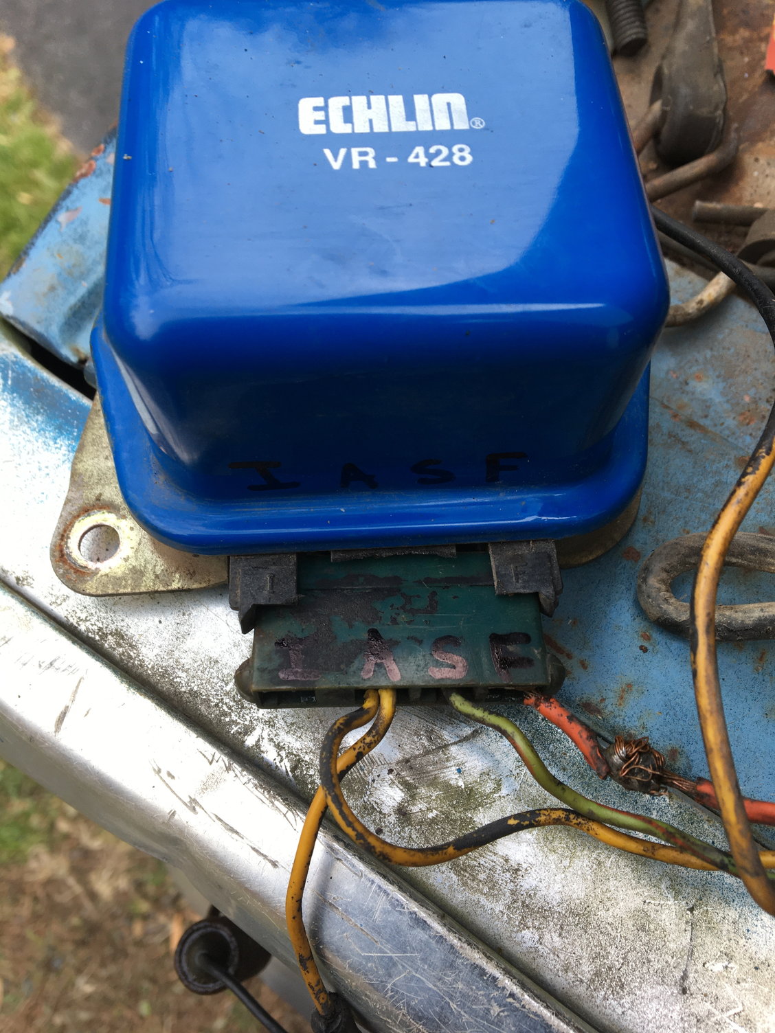
Best deal on goodyear air hose check this out httpsamznto3b5cJvy. Echlin vr -1001 vr -1017 kem kvr 162 t napa vr 1001 prestolite 8405 vsh 6201 jy r c p inc.
 3g Alternator Swap A Bit Confused Ford Truck Enthusiasts Forums
Remove the fuel pump fuse.
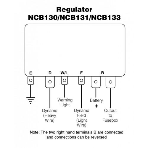
Echlin voltage regulator wiring diagram. Interconnecting wire routes may be shown approximately where particular receptacles or fixtures must be on a common circuit. Chinese voltage regulator wired up to honda gx clone with charge coils. This sensor is located inside of the regulator itself.
Voltage 120 VAC 90 140 VAC 1 phase 2 wire 5060 Hz Output Voltage 100 VDC 120 VAC input Current Continuous 8A Intermittent 10A for 10 sec Resistance Min. Pickup in Store not currently available. Select Vehicle Filter Results By Reset Filters.
Echlin voltage regulator wiring diagram wiring diagram is a simplified agreeable pictorial representation of an electrical circuit it shows the components of the circuit as simplified shapes and the capacity and signal links together with the devices. We pulled the old voltage regulator off. Throughout the years Ford has.
Heating Cooling - EngTrans. P8-405a 12v b-circuit aim ar -1073 amsco pa -244 cpc vrme -280 echlin vr -1001 vr -1017. Results for voltage regulator Select a vehicle for exact fit parts Select New Vehicle Select New Vehicle.
85-05 Four Wire Pigtail Three Wire Pigtail cont NE11211 VRC428 Voltage Regulator Pigtail. 65L Diesel Fuel Injection Pump 2002-94. How to convert a tractor from 6 volt to a 12 volt system - 62310 Feel free to donate with crypto below if you found this video helpful.
Many of those were later converted to the 8N type generator and voltage regulator so this Two small screw terminals on the side of the generator are for Ground. Voltage regulator connector wiring diagram. The voltage regulator is built into the alternator.
R1 and R2 is adjusted to program the desired output voltage. The LM338 has an output voltage range between 12V and 30V and it can deliver output current well over 5 Ampere. Echlin voltage regulator wiring diagram wiring diagram Architectural wiring diagrams appear in the approximate locations and interconnections of receptacles lighting and long-lasting electrical services in a building.
Each voltage regulator is a direct fit replacement that replaces OE damaged units providing accurate regulating charging voltage that the alternator produces. The PCM will control the voltage set point through the GEN-COMGENFDC wire depending on what the regulator reports to PCM. Being old enough to remember these electrical systems Memmolo threw in his two-cents in the trouble-shooting department.
This is the most simple voltage regulator circuit diagram in our website. Just got an IC LM117 and 4 passive components. 25 volts Adjustable regulator using LM117.
Six-volt generators and 12-volt alternators require current at voltages. Each connector and terminal is constructed with OE quality materials to ensure an exact fit connection resume peak conductivity to the engine wiring harness and resulting in a precise. Fluctuation in voltage can harm these electrical mechanisms.
Two Wire Socket Three Wire Socket Five Wire Pigtail Six Wire Pigtail Seven Wire Pigtail Nine Wire Pigtail Ten Wire Pigtail Eleven Wire Pigtail Sixteen Wire Pigtail EC113 Idle Air Control Valve Ignition Control Module Connector. I need a wiring diagram or pin identification for a NAPA VRSB regulator. The regulator set point 125-16 volts is established by a temperature sensor that calculates battery temperature.
The regulator in non-adjustable and must be replaced as a unit. 16022019 16022019 3 Comments on Wiring Diagram For 6v Tractor Voltage Regulator Positive Ground Solenoid Start This walk-thru is based on the original 8N tractor 6 volt wiring. A tractors regulator takes the voltage provided by the battery manages it.
13286 solid state vrp 405. On early 3800 models the fuse is located in the fuse panel on the left side of the instrument panel and marked FP On later models it is located below the relay panel on the drivers side of the. Isolated DCWiring diagram for NAPA VRSB regulator.
Posted by av8 on Apr 24 Want Answer 0. 15 ohm Voltage Regulation 1 with 4 engine governing Voltage Build-up Residual voltage at AVR terminal 5 VAC Thermal Drift 003 per C change in AVR ambient. If the wiring is all original check two things.
Wiring diagram discussion in the Farmall International Harvester IHC forum at Voltage Regulator. Keep checking back as we continue to add additional products and categories. A voltage regulator takes current from a battery with oscillating voltage and puts out constant voltage.
First unplug the voltage regulator and see if the engine shuts off with the key as normal. GM Cars Trucks. 65L Injection Pumps.
Echlin voltage regulator wiring diagram wiring diagram Architectural wiring diagrams show the approximate locations and interconnections of receptacles lighting and permanent electrical services in a building. Interconnecting wire routes may be shown approximately where particular receptacles or fixtures must be on a common circuit. Remove the gas cap to relieve the fuel pressure.
Voltage regulator for portable generator wiring diagram. GEN light blue to generator A.
Voltage Regulator Wiring Ford 460
 Lucas Voltage Regulator Wiring Diagram 2003 Buick Lesabre Wiring Diagram Vww 69 Yenpancane Jeanjaures37 Fr
 Echlin Voltage Regulator Wiring Diagram Chilton S Wiring Diagram 2004 Monte Carlo Controlwiring Losdol2 Blong Jeanjaures37 Fr
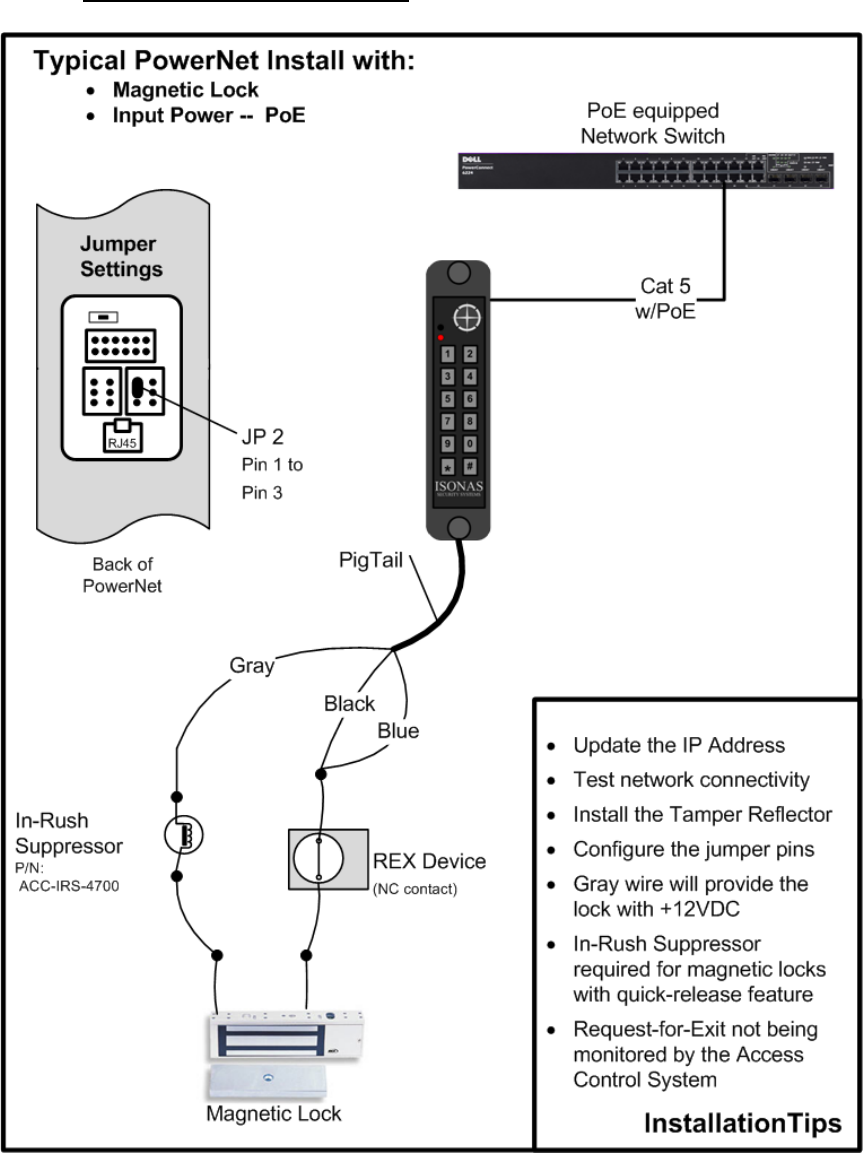
 Isonas Wiring Diagram Echlin Voltage Regulator Wiring Diagram Fords8n Losdol2 Jeanjaures37 Fr
 Voltage Regulator Napa Echlin Parts Ech Vr1010
0 Comments