Homemade 12v to 33000v flyback transformer flyback driver with transistor 5200clist of components1. RGB LED light wall washer circuit diagram.
 Flyback Transformer Driver Sok Pa Google Electronic Circuit Projects Electronics Circuit Electrical Circuit Diagram
Explain and interpret information found on transformer name plates.

Fly back transformer driver wiring diagram schematic rise. This supplyalso called a power converterhas two distinct operating phases. Indentify the schematic symbols of potential and current transformer. Flyback Transformer Driver for Beginners.
This EBay listing shows a typical 1000 Watt induction heater. The schematic has been updated to include basic transistor protection in the form of a capacitor and diode. If you get really good MOSFETs it might be even possible to run your ZVS flyback driver infinitely.
Most computer monitors and newer televisions use flybacks which have the high voltage rectifier built in. Unlike the simple 555 timer flyback drivers The ZVS flyback drivers will allow you to run your flyback transformers for much longer periods of time before the MOSFETs overheat. By Natalya Shnayder On February 22 2021 In Wiring Diagram 141 views Fly Back Power Supply Switching Schematic 417 5 117 votes Top Suggestions Fly Back Power Supply Switching Schematic.
Identify transformer polarity using dot and conventional labeling. The step 9 page going further now includes a way to measure these illustrious voltage spikes with a regular volt meterIntro This. A You need a 24 V DC power supply and a digital voltmeter set in 20 V range.
So I give you a simple method to find this 0v pin. The pin diagram is shown in the above image. May 12 2019 - Flyback Transformer Driver for Beginners.
Or until the circuit is interrupted Video of it working. During each cycle when the input voltage is applied to the primary winding energy is stored in the gap of the core. Car LED light driver circuit diagram.
They are used for generating high voltage for the CRT which is needed to create an electric field which in turn accelerates electrons towards the screen which finally excite phosphors and create the image. A flyback transformer is a coupled inductor with a gapped core. Flyback transformers are found in monitors TVs or anything with a CRT and are sometimes known as Line OutPut Transformers or just LOPT.
The schematic has been updated to include basic transistor protection in the form of a capacitor and diode. Compare and contrast the performance of three phase transformer connections. The primary polarity is set to 2x12 turns of the diameter of the wire 04mm while the secondary polarity is set to 700 turns of wire 01mm.
LED light circuit protection diagram. It will look more like your high Sparks but it will definitely be much safer. The schematic has been updated to include basic transistor protection in the form of a capacitor and diode.
The photo on the right below shows the wires before winding them on. LED power supply without transformer circuit diagram. The step 9 page going further now includes a way to measure these illustrious voltage spikes with a regular volt meterIntro This instructa.
List characteristics on these devices and explain how. For inverter transformer I preferred to use EE core based transformer keeping the middle column cross-section of 20 25 mm2. It will still equal 4000 x 01 400 wattsThis can be done with another transformer before the rectifier circuit of the flyback transformer.
This is a instructable that contains scematic and pictures of a single transistor flyback driver. The SS and FB pin has low voltage tolerance. Flyback transformers are used to provide voltage transformation and circuit isolation.
Flyback Converter Circuit Diagram and working. The main HV output is simple to find. The circuit initially was used as a high voltage driver for CRT flyback coils.
AC 230V LED Driver Dimmer circuit diagram 0-10V or Wireless isolated. The flyback design is a switched-mode power supply SMPS thats been used for 70 years and still going strong. There are several different types of flybacks and any device using a cathode ray tube will contain one this includes oscilloscopes televisions monitors and others.
This video shows tests on a 1000 Watt induction heater board. Dimmer LED circuit diagram 80W power supply. Preferably make it 4000 volts and 01 amperes.
The air gap of 05mm thickness is place in the mid column. LED light circuit protection diagram. We need to be careful about the absolute maximum rating of the IC.
Here is an interesting site that discusses the driver when used as a. 1x breadboard 1x NPN transistor with heat sink and a fan 1x 22 Ohm resistor 1x 220 Ohms resistor 1x transformator or round ferrite. If its possible try to convert the high current to high voltage.
It is then transferred to the secondary winding to provide energy to the load. Later the same circuit was employed to drive induction heating coils. This is the big red cable with the suction cup but you need to find the 0 V pin of the secondary coil on the flyback transformer.
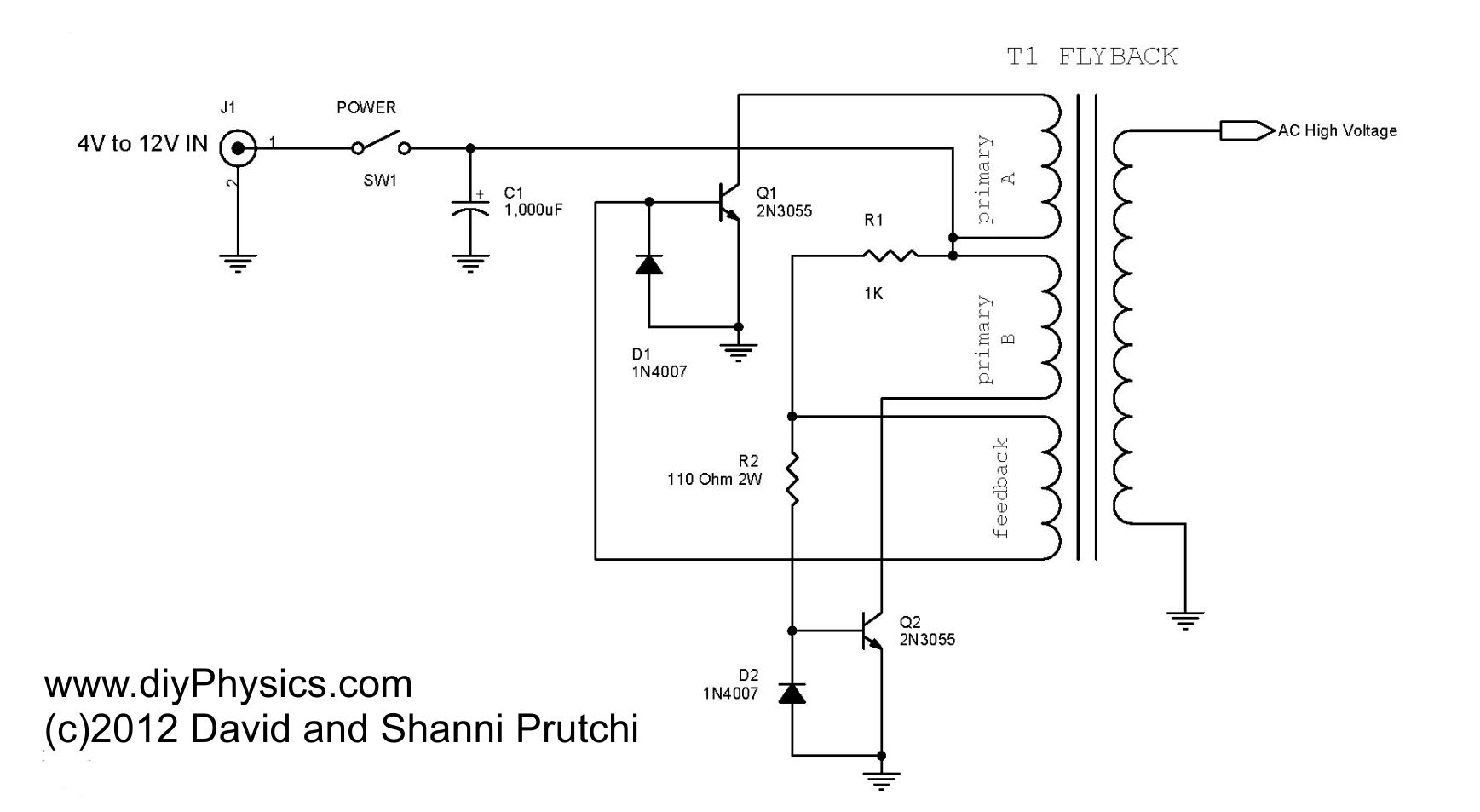
Both coils are center tapped meaning that theres an extra wire coming from the center of each coil. The step 9 page going further now includes a way to measure these illustrious voltage spikes with a regular volt meterIntro This instructa. The heart of the circuit is a ferrite-cored flyback transformer.
Jan 14 2019 - Flyback Transformer Driver for Beginners. By using this LM5160 we will simulate a 12V isolated power supply based on the following spec. The flyback transformer didnt have any coils on the core so as you can see below I added two the primary coil black and the feedback coil red.
 Mazzilli Zvs Flyback Converter Circuit Download Scientific Diagram
 Loneoceans Laboratories Flyback Driver Circuits
 Pulse Transformer Theory Gowanda Electronics
 2n3055 Flyback Driver For High Voltage Sparks
0 Comments